14F-6, No. 79, Sec. 1, Xintai 5th Rd, Xizhi Dist., New Taipei City, 22101 Taiwan (R.O.C.)
Tel: 886-2-2698-3877
Fax: 886-2-2698-4089
email : [email protected]


This series will be discontinued on January 1, 2025, with product services continuing for 5 more years. The replacement model is the 7750 series.
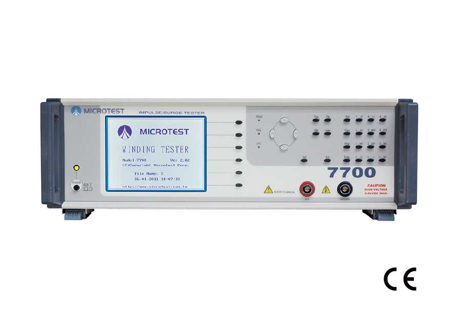
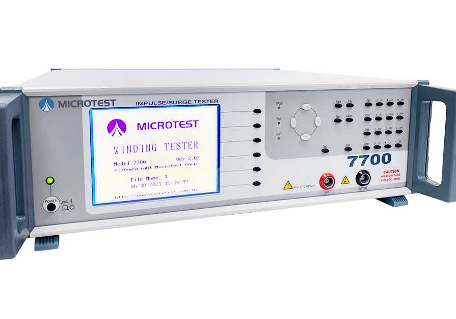
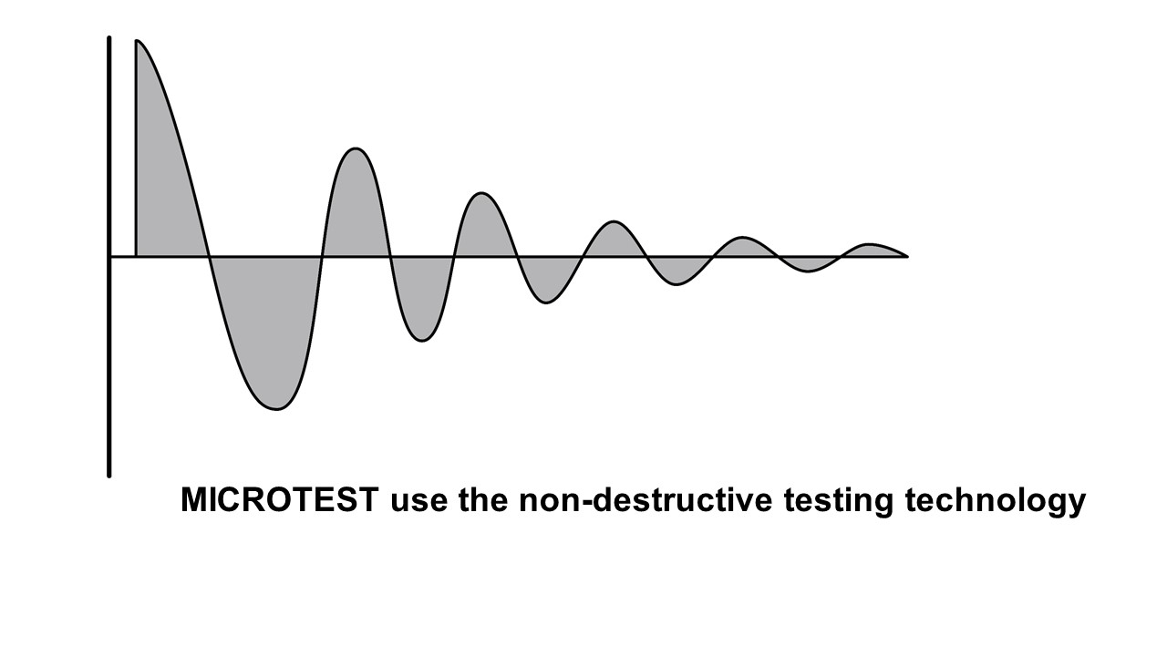
MICROTEST 7700 Impulse Winding Tester offers pulse voltage outputs ranging from 200V to 5000V. It utilizes damping attenuation waveforms generated by L/C resonance to analyze magnetic components for defects such as short circuits between coils or between layers of winding wire. The tester provides various comparison modes, including total area comparison, area difference comparison, corona count comparison, jitter count comparison, and waveform comparison. These modes help identify and detect faulty products accurately.
Selection
| Model | 7710 | 7720 | 7703 | 7713 |
| Test Channel | 2 | 8 | 2 | 2 |
| Impulse Voltage | 200V-10000V | 200V-5000V | 100V-5000V | 200V-10000V |
| Lowest Inductance | 100uH | 50uH | 0.5uH | 0.5uH |
| HARM analysis | - | - | ● | ● |
| HFLT analysis | - | - | ● | ● |
SPEC
| Model | 7700 | |
| Test Channel | 2 | |
| Impulse Voltage | 200V-5000V(可程式) | |
| Impulse Voltage Accuracy | ±2% | |
| Lowest Inductance | 50uH | |
| Measurement Time | 50mS | |
| Provides 5 waveform comparison | ||
| Total area comparison |
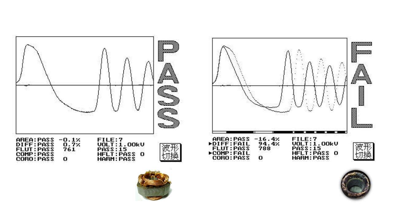
When layer short happened, the loss of power on coil increase, the resonance damping coefficient increase, resonance amplitude decrease, the total area decrease. These are the basic parameters we check layer short. By calculating and comparing the deference of area between golden sample and DUT. |
|
| Differential area comparison |
Add up the difference between normal wave and DUT wave call “ Area differential”. By calculating and comparing the deference of area between golden sample and DUT. To determine the degree of waveform overlap. |
|
| Wave comparison | Set a acceptable wave range, if the DUT’s wave is in this range shows “pass” otherwise, “fail” This parameter can judge both amplitude and phase of resonance wave. This can increase the detection capability of layer short. |
|
| Corona comparison | In pulse test, the insulation defect will cause discharge and create corona. This function is able to count the times that corona happened base on the degree of deviation. Detect the discharge phenomenon on the coil. |
|
|
Flat comparison |
If the layer short happened, the waveform will tremble. Therefore, the instrument will quantize and compared it. | |
SYSTEM
| PLC Remote Control | Test、About |
| PLC Remote Output Signal | PASS、FAIL、HV Output、Testing |
| Built-in Storage | 200 sets testing waveform |
| Power Supply | Voltage:98Vac-132Vac 或192Vac-264Vac |
| Frequency:50/60Hz ±5% | |
| Power consumption | 300VA |
| Environment | Temperature:10℃-40℃ |
| Humidity:20-90%RH | |
| Dimension | 435x145x522 mm (W*H*D) |
| Weight | 8 Kg |
| Interface | RS-232、Remote、Printer |
| Display | 5.7" dot-matrix (300*240 ) |
Introduction of Impulse Tester
Impulse Winding Tester use the comparison of pulse to measure the DUT. The instrument provide high voltage to do the instant pulse test and record the wave. Compare with the golden sample to define the product.
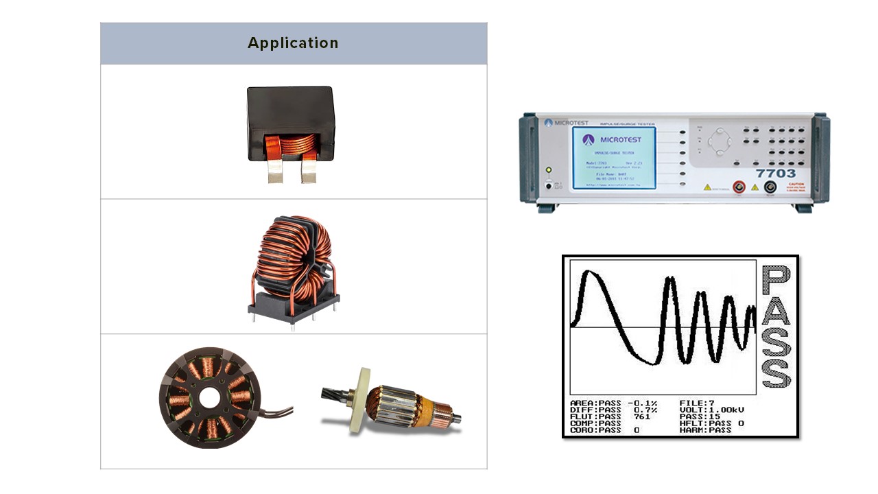
| Application | |
| Low inductance coil | |
| High power inductance | |
| Transformer | |
| Motor stator | |
| Motor rotor | |
| Winding component |
Why do we need impulse tester for producing motor/transformer?
Impulse Test = Quality and product life test
The small defection is hard to find at low voltage test station. As the DUT goes to the final assembly test, the defect may show up. This will higher the cost of production.
Motor and transformer usually work under high voltage. If we add impulse test in the product line, this may prevent the malfunction or burn on motor.
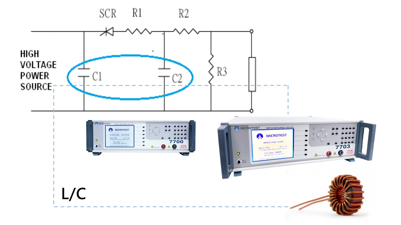
| L | is the DUT coil |
| C1, C2 | are the resonant capacitors in the instrument |
| R1, R2, R3 | is the resistant in the instrument and the DUT |
| Technology of Detect Layer Short | |
| → 1 | Charge the C1 capacitor to the certain testing voltage level. |
| → 2 | Trigger the SCR by pulse |
| → 3 | DUT will resonate with C1 and C2 |
Technology of Detect Layer Short
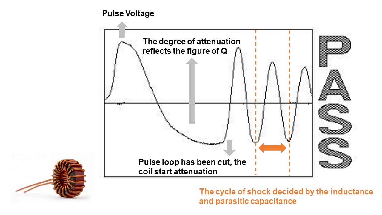
“Pulse voltage and waveform comparison” is the way we detect layer short. The pulse voltage is non-destructive/instant voltage that apply on both side of winding and detect the DUT without damage it. By compare the wave with the golden sample, we can judge the DUT.
Damping wave under L/C resonate comes from the feature change of defect coil.
By comparing the wave of damping attenuation between golden sample and DUT
Provides 5 waveform comparison
Standard Accessories
| Power Cord | |
| High voltage tests cable (red and black ) | 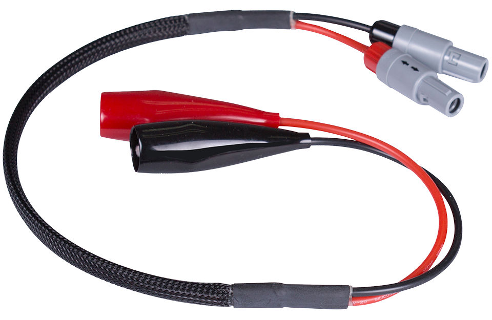 |
| D-Sub footswitch (F760001) | |
Optional Accessories
| PC Link Software | |
| RS-232 Cable | |
| Remote Cable |