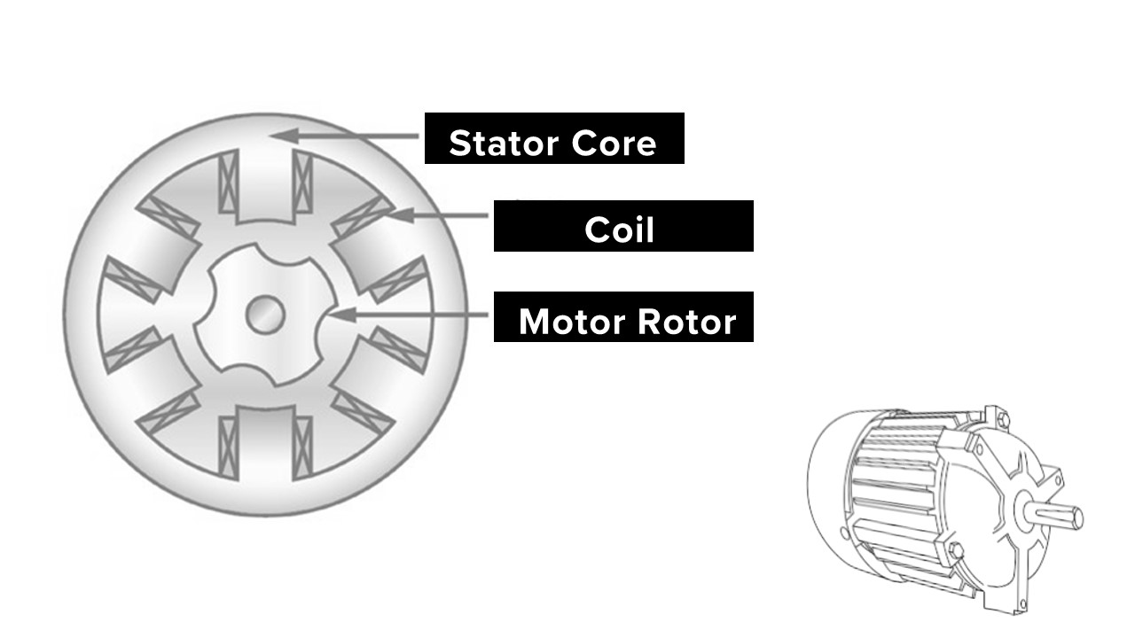
Rotor Coil and Rotor Core
Rotor core is made by 0.5mm silicon steel. Medium and small AC motor’s rotor core are mostly apply on shaft. Huge motor usually apply on steady than stick on the shaft.
Rotor coil is to conduct current and create inductance. There are two type of winding, squirrel-cage and wound.
Squirrel-cage rotor is self-closing winding. There is a conduct bar in each steady and connect both side.
Wound winding rotor is insert insulate wire into core as three phase winding set and connect on slip ring. And lead the current by brush.
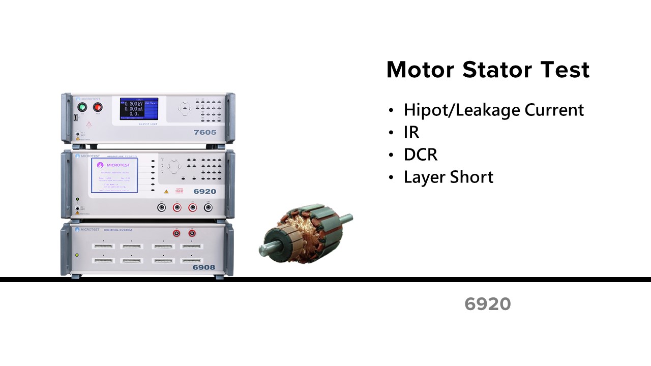
Quality Issue on Enameled Process
- The process of covering insulation paint may scratch the wire.
- Crack on wire
Process of Winding
- Hook/ Out of order/ Envelope
- Winding Cross
- Tin attached

Uneven DCR happen in 3-pase motor, this will cause uneven rotate.
MICROTEST 4-Wire DC Resistance measurement will be more accurate than others.

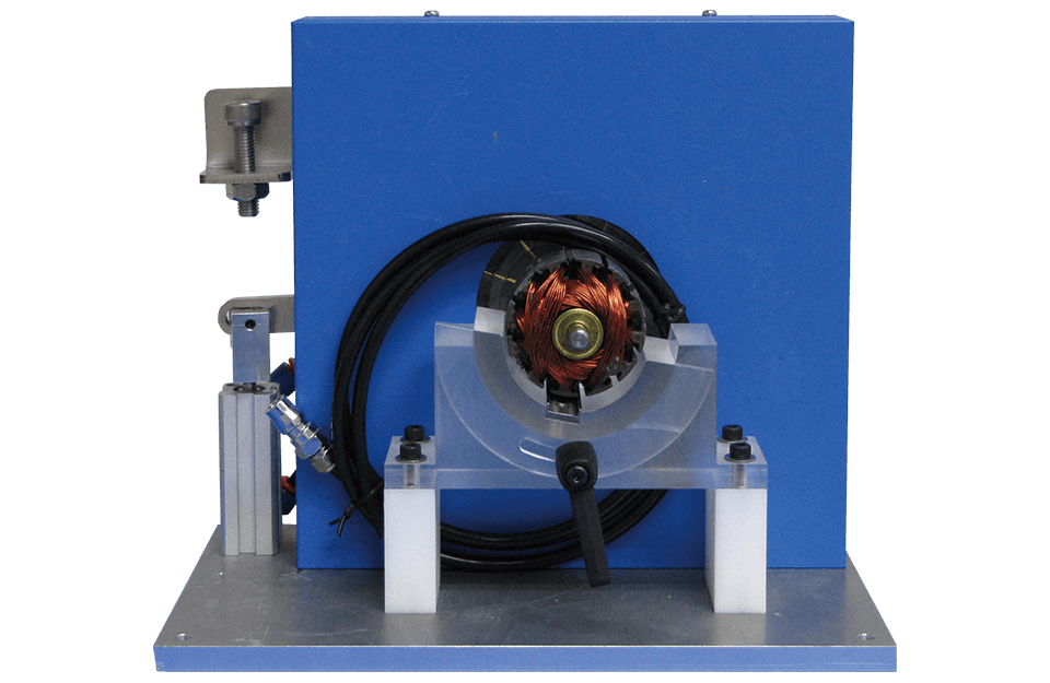
Customized test fixture for rotor coil
For Enameled Winding of Motor
- Conduct coil’s quality issue.
- Layer Short Between Winding
- Short on cross winding
- Pin Short
- Insulation Defect
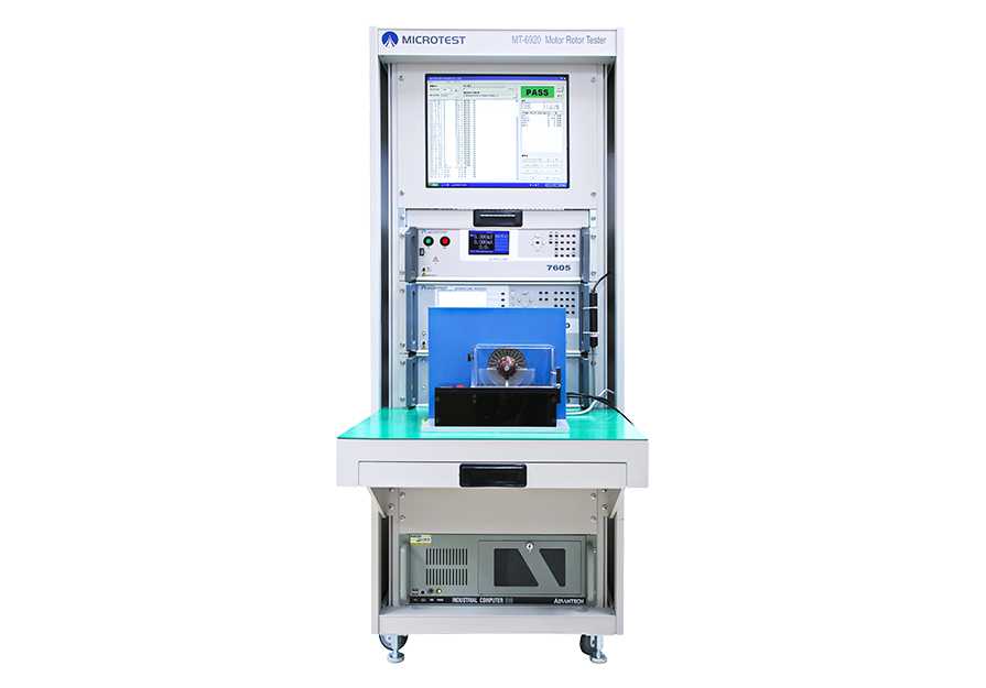
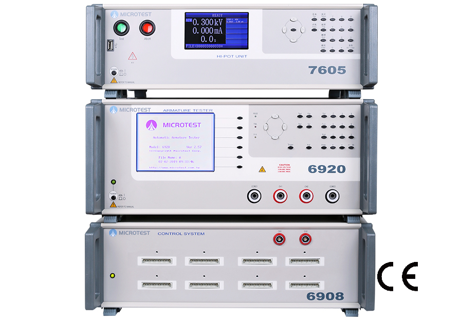
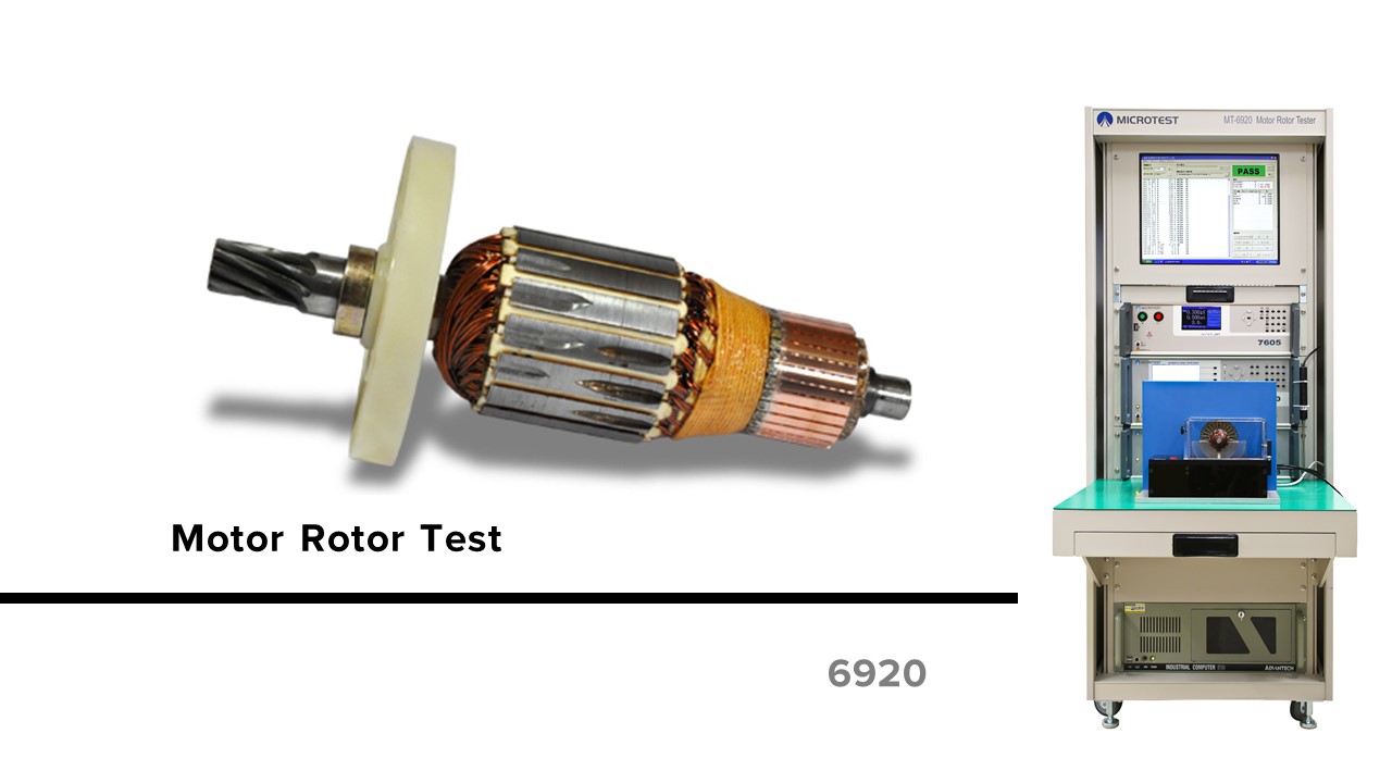
MICROTEST Motor Rotor Testing System is One-Step-Test Function
Low Voltage Electrical Test + Hipot Test + Layer Short + Resistance Welding Test
Important Parameter for Quality of Coil
- Regular motor is winding on Silicon steel sheet
- Prevent the electricity from enameled wire to motor
- Put a insulation material on silicon steel sheet
- Insulation paint on enameled wire
- Short might happened while the current is passing the defect winging coil.
- Method of Detect Leakage Current
Inspect leakage current and Hipot by using Hipot tester. Connect one end to coil winding, and the other to silicon steel. Compare the leakage current and insulation resistance under AC and DC voltage.
- Inspect micro feature of AC Leakage Current
The enameled wire on motor include some tiny parasitic capacitance, this feature will create leakage current because of resistance. Under AC source, capacitance is a impedance item. This may make the test result include the leakage current from the hipot tester. If the DUT has low AC leakage current, it must concern capacitance , frequency, and the voltage we use.
The inside of insulation material will discharge under high voltage test, because of the poor insulation. In this case, temporary or inconsistence discharge on DUT will happen.
Arc detection is a kind of geometric, non-constant test. The result will affected by the impedance or capacitance and current by time.

Introduction of Impulse Tester
Impulse Winding Tester use the comparison of pulse to measure the DUT. The instrument provide high voltage to do the instant pulse test and record the wave. Compare with the golden sample to define the product.
Why do we need impulse tester for producing motor/transformer?
Impulse Test = Quality and product life test
The small defection is hard to find at low voltage test station. As the DUT goes to the final assembly test, the defect may show up. This will higher the cost of production.
Motor and transformer usually work under high voltage. If we add impulse test in the product line, this may prevent the malfunction or burn on motor.
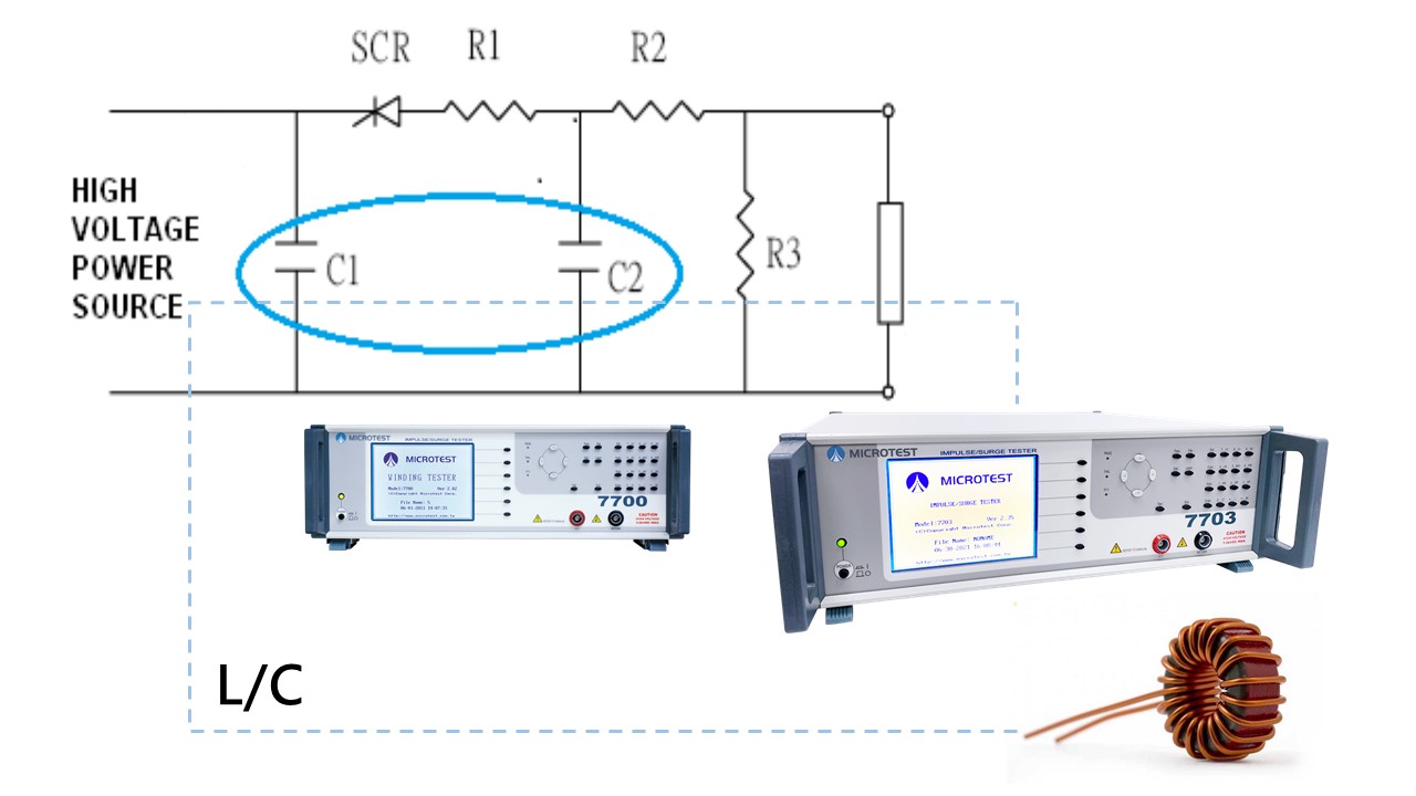
| L |
is the DUT coil |
| C1, C2 |
are the resonant capacitors in the instrument |
| R1, R2, R3 |
is the resistant in the instrument and the DUT |
| Technology of Detect Layer Short |
| → 1 |
Charge the C1 capacitor to the certain testing voltage level. |
| → 2 |
Trigger the SCR by pulse |
| → 3 |
DUT will resonate with C1 and C2 |
Technology of Detect Layer Shor
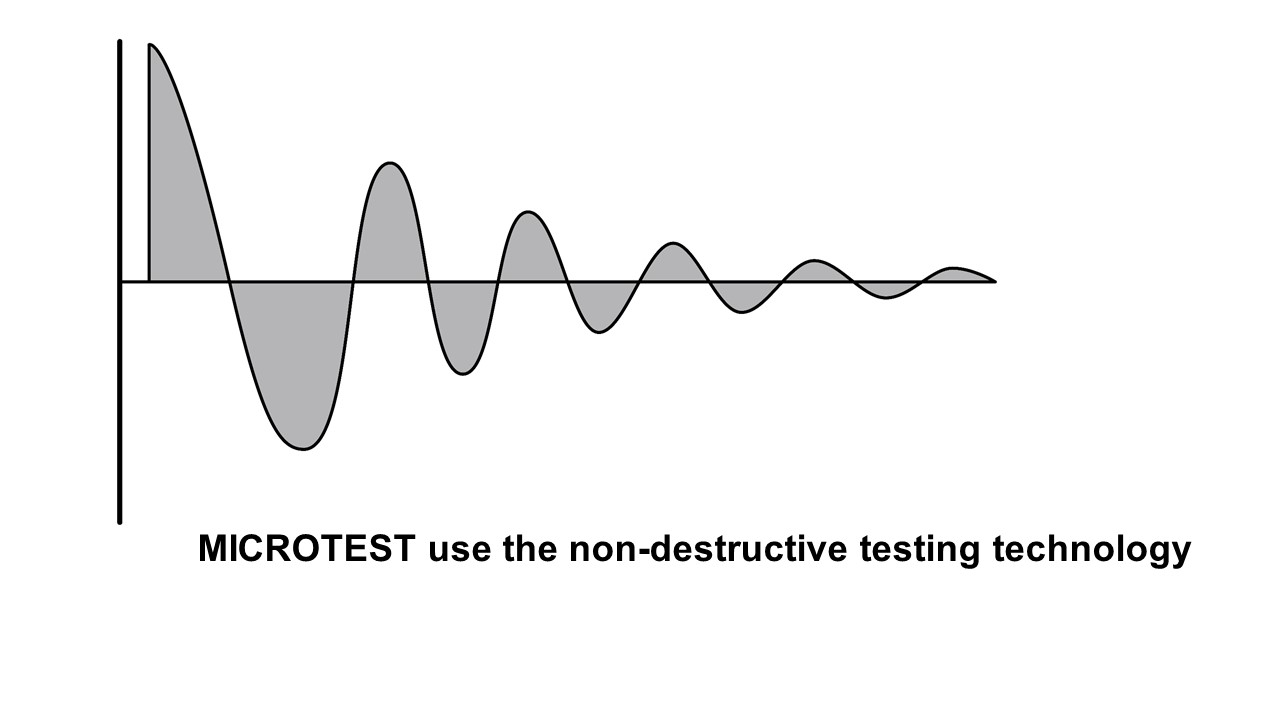
“Pulse voltage and waveform comparison” is the way we detect layer short. The pulse voltage is non-destructive/instant voltage that apply on both side of winding and detect the DUT without damage it. By compare the wave with the golden sample, we can judge the DUT.
Damping wave under L/C resonate comes from the feature change of defect coil.
- Inductance of coil
- Q rate
- Turn ratio of coil(voltage different)
- Material of core
- Layer short in the coil

By comparing the wave of damping attenuation between golden sample and DUT
Provides 5 waveform comparison
- Total area comparison
- Differential area comparison
- Wave comparison
- Flat comparison
- Corona comparison


