14F-6, No. 79, Sec. 1, Xintai 5th Rd, Xizhi Dist., New Taipei City, 221432 Taiwan (R.O.C.)
Tel: 886-2-2698-3877
Fax: 886-2-2698-4089
email : [email protected]


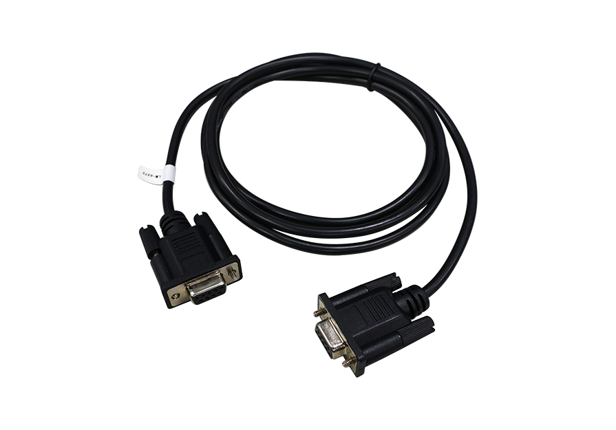
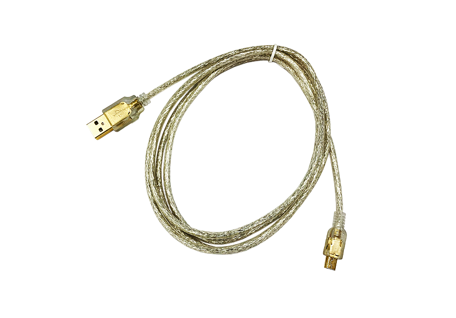
MICROTEST 6632S Impedance Analyzer offers a wide frequency range of 10Hz to 50MHz for measuring the impedance characteristics of components and materials. Support Equivalent Circuit Analysis function to analyze the impact of parasitic components on impedance. The measured parameters include |Z| (impedance), |Y| (admittance), θ (phase angle), X (reactance), R (series/parallel resistance), G (conductance), B (Susceptance), L (inductance), D (dissipation factor), Q (quality factor), DCR (DC resistance), C (capacitance), ESR (equivalent series resistance), ε (relative permittivity), and μr (relative permeability). It supports both Meter mode and Sweep Analysis mode, allowing measurement results to be displayed in numeric or graphical formats. It supports LAN/USB Host/USB Device/RS-232/GPIB(Optional) communication interfaces, making it compatible with automation equipment or human-machine interfaces (PLC).

The precision impedance analyzer 6632S has seven frequency options(10Hz to 1/3/5/10/20/30/50MHz).

Evaluation impedance characteristics of RFID / NFC / automotive wireless of antennas

Equivalent Circuit Analysis (Option)
It has seven different models, combine with different types of parameters ( R, L, C) help customers model the impedance versus frequency characteristics and self-resonant frequency (SRF).

The induction coil for wireless charging in a mobile phone. Due to the manufacturing process, the wiring density layout from the induction coil will affect the original capacitance. The size of the parallel equivalent capacitance in the coil is the key to determine whether the product can be successful in high frequency application. It can affect the receiving function/wireless charging of an antenna. With this element analysis, we can accurately determine the RLC value to ensure the quality of the induction coil.

Model E is suitable for measuring and analyzing the resonators, piezoelectric element or transducer. The two-resonance frequency characteristic diagram presented above is suited for Model E.

List Mode
50 groups of list mode setting (Each group contains up to 15 steps).

Four Parameters Displayed Simultaneously
7.0”TFT, 800x480 color screen, and four parameters can displayed simultaneously.
Measure Inductor (DCR)
Inductor coil turns and winding materials will affect DCR value. The key parameters for inductor are Ls / Lp / Q / SRF / DCR.


Evaluation of DC bias voltage characteristics with semiconductor wafer or ceramic multilayer capacitors.


Magnetic Material Test Fixture (FX-0000C8)
Using the magnetic material test fixture for measuring of permeability of various toroidal cores or ferrite cores and electromagnetic shielding coating materials, 6632 built-in formula to directly calculate the permeability coefficient value μr

Dielectric Material Test Fixture (FX-0000C7)
Liquid Dielectric Material Test Fixture (FX-000C20)
Using the dielectric material test fixture for measuring PCB board or ceramic board. 6632 built-in formula to directly calculate the material dielectric value εr ', εr ".Using the liquid dielectric material test fixture for measuring the characteristics of electrochemical materials.

Testing PC board inductance coil.