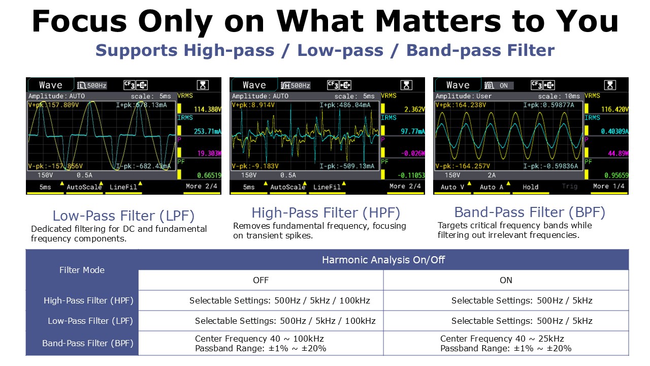
Exclusive Super Filter Function: High-pass / Low-pass / Band-pass Filters
Engineers can select the appropriate frequency range based on actual test requirements to analyze power parameters within the target frequency band.

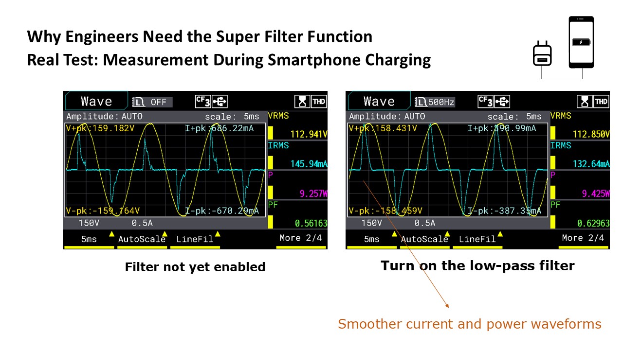
The switching power supply of the charger, the load-side device, and the intermediate cable may introduce high-frequency noise and low-frequency disturbance signals, which affect the accuracy of the power waveform.
By enabling the low-pass filter, high-frequency noise generated by the charger is effectively suppressed, resulting in smoother average power and current waveforms. This is suitable for observing overall charging efficiency and load stability.
Up to 100-Order Harmonic Analysis with Odd and Even Harmonics Display

MICROTEST 7140 Power Analyzer meets the Harmonic measurement requirements of IEC61000-4-7 standards, supporting harmonic analysis up to 100 orders. The measurement results can be displayed as either numerical values or bar charts, allowing for precise analysis of key harmonic parameters such as voltage, current, power, voltage distortion percentage, power distortion percentage, voltage phase angle, and current phase
angle.

In harmonic analysis mode, engineers can choose to display odd-order harmonics or even-order harmonics.
Focusing on odd-order harmonics helps quickly identify issues such as nonlinear loads or voltage distortion, allowing for precise pinpointing of factors affecting power quality.
Filtering evenorder harmonics is effective for diagnosing potential risks such as load imbalance or equipment aging, simplifying data analysis and enabling engineers to quickly get to the root of the issue.
|Displaying Odd-Order Harmonic Analysis
Harmonics with Even Multiples of the Rated Frequency (Even-Order Harmonics)
Identifying Potential Asymmetry or Specific Equipment Issues
|Even Harmonic Analysis Display
Harmonics at Odd Multiples of the Rated Frequency (Fundamental Frequency)
Evaluating the Impact of Non-Linear Loads on the System
The instrument uses independent measurement modules, allowing engineers to simultaneously perform harmonic analysis and integration, enabling real-time monitoring and analysis.


Power Integration Mode
In Power Integration Mode, the MICROTEST 7140 accurately measures current integration (Ah) and energy (Wh) over a time range of up to 10,000 hours. It allows for long-term monitoring of equipment's energy consumption and current demand, making it ideal for durability testing of motors/rotating machinery. The instrument also supports data storage via the standard USB Host communication.
With its independent measurement modules, the instrument can simultaneously perform harmonic analysis and integration in any screen background, enabling real-time evaluation of harmonic effects in the system.
Moving the Timeline for More Flexible Trend Analysis, Quickly Focusing on Specific Moments or Sections

MICROTEST 7140 Power Analyzer supports trend chart analysis, allowing for a more intuitive view of how power parameters change over time through the timeline. This feature enables engineers to quickly and accurately pinpoint data variations at specific moments.
- Transient Division
- Trend Prediction and Diagnosis
- Efficiency and Performance Verification
- Comparative Analysis
- Data Logging and Reporting
Front-Facing Voltage/Current Input Terminals for Easy Connection

The voltage/current measurement input terminals adopt a front-facing design, enabling quick and convenient connection with the F71201 fixture box. The F71201 connection cables can be directly connected to the 7140 Power Analyzer, allowing DUTs (such as AC plugs) to be plugged into the fixture box for plug-and-play functionality, eliminating the hassle of manual wiring.
Support Switching Between High and Low Current Measurement Modes –Eliminating Manual Wiring

Most power measurement instruments cannot automatically adjust wiring to compensate for the internal resistance of current and voltage meters, which affects power consumption measurements. Engineers typically need to use the correct wiring method (U-I / I-U wiring) to ensure precise standby power measurement.
The MICROTEST 7140 supports manual switching between high and low current measurement modes (when used with the F71201 test fixture and for currents below 15A), eliminating the need for manual rewiring and improving measurement efficiency.
|High-Current Mode
When measuring high-current products, the F71201 test fixture allows switching to high-current mode. The voltage measurement point is directly connected to the DUT (Device Under Test) to prevent voltage drop in the wiring loop, ensuring accurate power measurement without underestimation caused by high-current load conditions.
|Low-Current Mode
When measuring low standby power products, switching to small current mode automatically compensates for the 7140 voltage input internal resistance of 1.66MΩ, ensuring that the measured power approaches 0W. This feature is particularly useful for standby power evaluation, providing high accuracy in ultra-low power measurements.
In Meter Mode, up to 4/8/16 sets of parameters can be displayed at once

MICROTEST 7140 features a 4.3”TFT LCD display with 5-digit measurement readout. In Meter mode, it can simultaneously show 4/8/16 sets of parameters.
It offers ultra-high precision for voltage, current, and power measurements, achieving an accuracy of ±0.05% of the reading ±0.05% of the range.
Automatic PASS/FAIL Judgment

MICROTEST 7140 supports Comparison Mode, allowing users to set upper and lower limit values. This feature is ideal for production line testing, where it can automatically perform PASS/FAIL judgment for multiple parameters, such as voltage, current, and power, based on the defined
limit values.
Simultaneous Monitoring of Maximum and Minimum Values for 4/8 Parameters

MICROTEST 7140 is capable of simultaneously monitoring 4 or 8 parameters, displaying their maximum and minimum values. This helps engineers efficiently track fluctuations and variations in power-related parameters. Additionally, it supports graphical display and features a simple oscilloscope function to observe voltage and current waveforms. With its USB Host storage interface, users can directly capture waveform screenshots and record values without the need for an external oscilloscope.
Effective Analysis of AC Power Parameters with DC Characteristics in Voltage/Current

Due to grid fluctuations, the waveform of AC power may not always be a perfect sine wave. When measuring AC parameters, the MICROTEST 7140 can simultaneously display the DC component within the AC voltage and current data. This provides a more comprehensive view of power quality, assisting engineers in optimizing and analyzing power supply designs.
Circuit and Frequency Filtering Function

With the MICROTEST 7140 supporting filtering functions, unwanted frequencies in the signal can be filtered out during measurement, leaving only the signals within the target frequency range. This results in cleaner waveforms and more precise measurements of important power-related parameters in power systems.
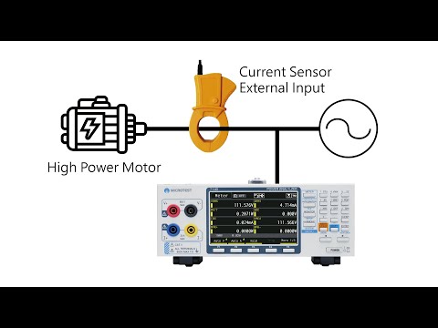
Current Sensor Input

MICROTEST 7140 provides a maximum input of 800V and 30A. For current measurement needs exceeding 30A, voltage input-type current clamps or current sensors can be purchased for testing.
| High Current Measurement Solution |
| Clamp- on Tr ans f ormer |
Cur r ent Sensor |
|

|

|
| AC 100A/ 1V |
AC 500A/ 4V |
| Bandwidth 5kHz |
Bandwidth 50kHz |